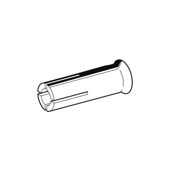
Drop-In Anchor AN ES
Application
Drop-In Anchor for single fixing in non-cracked concrete and multiple fixing in cracked concrete. Suitable for fixing pipelines, channels, etc. meeting the respective approval requirements. The anchor must only be used for dry interiors. For damp locations and outdoor constructions the stainless steel version is required.
- No special drill required
- Setting tool for distance-controlled forced expansion
- Suitable for push-through mounting
Installation
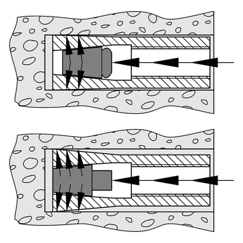
As expansion tool use the respective Setting Tool for Drop-In Anchor or the Plug-on Setting Tool ASW. The "intelligent" expansion cone facilitates the mounting with bore dia. tolerances or varying concrete quality. By the controlled deformation of the cone during installation, the needed edge and centre distances are decreasing considerably.
Technical Data
Single fixing:
Extract from application conditions of ETA-10/0257
Permissible loads according to EN 1992-4 without influence of centre and edge distances. Overall safety factor is taken into account ( YM und YF ).
| Anchor size | M8x30* | M8x40 | M10x30 | M10x40 | M12x50 | M16 |
|---|---|---|---|---|---|---|
| Nominal diameter of drill d0 = [mm] | 10 | 10 | 12 | 12 | 15 | 20 |
| Depth of bore hole h0 = [mm] | 30 | 40 | 30 | 40 | 50 | 65 |
| Installation torque Tinst = [Nm] | 8 | 8 | 15 | 15 | 35 | 60 |
| Diameter of clearance hole in the connecting element df ≤ [mm] | 9 | 9 | 12 | 12 | 14 | 18 |
| Thread length Lth [mm] | 13 | 20 | 12 | 15 | 18 | 23 |
| Min. screwing depth Lsdmin [mm] | 9 | 9 | 10 | 11 | 13 | 18 |
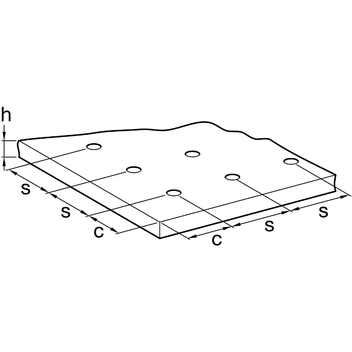
| Min. thickness of concrete slab hmin [mm] | 100 | 100 | 120 | 120 | 130 | 160 |
| Min. centre distance smin [mm] | 60 | 80 | 100 | 100 | 120 | 150 |
| Min. edge distance cmin [mm] | 95 | 95 | 115 | 135 | 165 | 200 |
| Perm. tensile load in non-cracked concrete (Screw 5.6 up to 8.8) | ||||||
| C20/25 [kN] | 3.2 | 3.6 | 3.2 | 4.9 | 6.9 | 10,2 |
| C25/30 [kN] | 3.6 | 3.8 | 3.6 | 5.5 | 7.7 | 11.4 |
| C30/37 [kN] | 3.9 | 4 | 3.9 | 6.0 | 8.5 | 12.5 |
| C40/50 [kN] | 4.5 | 4.4 | 4.5 | 7.0 | 9.8 | 14.5 |
| C50/60 [kN] | 5.1 | 4.7 | 5.1 | 7.8 | 10.9 | 16.2 |
| Lateral load (Screw 5.6) ≥ C20/25 zul. V [kN] | 3.8 | 3.9 | 3.8 | 4.1 | 9 | 16.8 |
| Lateral load (Screw 5.8) ≥ C20/25 zul. V [kN] | 3.8 | 3.9 | 3.8 | 4.1 | 11.1 | 18 |
| Lateral load (Screw 8.8) ≥ C20/25 zul. V [kN] | 3.8 | 3.9 | 3.8 | 4.1 | 11.1 | 18 |
| Perm. bending moment (Screw 5.6) Mzul [Nm] | 8.1 | 8.1 | 15.8 | 15.8 | 27.8 | 71 |
| Perm. bending moment (Screw 5.8) Mzul [Nm] | 10.9 | 10.9 | 21.1 | 21.1 | 37.1 | 94.9 |
| Perm. bending moment (Screw 8.8) Mzul [Nm] | 17.1 | 17.1 | 33.7 | 34.3 | 60 | 152 |
| Charact. centre distance scr [mm] | 90 | 120 | 90 | 120 | 150 | 195 |
| Charact. edge distance ccr [mm] | 45 | 60 | 45 | 60 | 75 | 97,5 |
| Loads under fire exposure steel ≥ 5.6 | ||||||
| Perm. load R30 perm. F [kN] | 0.9 | 1.8 | 0.9 | 1.8 | 3.2 | 4.7 |
| Perm. load R60 perm. F [kN] | 0.9 | 1.3 | 0.9 | 1.8 | 3.1 | 4.7 |
| Perm. load R90 perm. F [kN] | 0.8 | 0.8 | 0.9 | 1.2 | 1.8 | 3.3 |
| Perm. load R120 perm. F [kN] | 0.5 | 0.5 | 0.7 | 0.8 | 1.2 | 2.2 |
* Application for indeterminated static systems
Multiple fixing:
Extract from application conditions of ETA-10/0258
For the multiple use for non-structural applications. Permissible loads according to EN 1992-4 without influence of centre and edge distances. The overall safety factor is taken into account ( YM und YF ).
The maximum permissible load per fixing point may be less than the permissible load of the anchor, depending on national regulations.
| Anchor size | M8x25 | M8x30 | M8x40 |
|---|---|---|---|
| Nominal diameter of drill d0 = [mm] | 10 | 10 | 10 |
| Depth of bore hole h0 = [mm] | 25 | 30 | 40 |
| Installation torque Tinst = [Nm] | 8 | 8 | 8 |
| Diameter of clearance hole in the connecting element df ≤ [mm] | 9 | 9 | 9 |
| Thread length Lth [mm] | 12 | 13 | 20 |
| Min. screw depth Lsdmin [mm] | 8 | 9 | 9 |
| Standard/Min. thickness of component hmin1 / hmin2 [mm] | 100/80 | 100 | 100 |
| Min. centre distance smin [mm] | 50 | 60 | 80 |
| Min. edge distance cmin [mm] | 100 | 95 | 95 |
| Perm. tensile load cracked/non-cracked concrete | |||
| C12/15 and C16/20 [kN] | 1.2 | - | - |
| C20/25 to C50/60 [kN] | 1.9 | 1.7 | 2 |
| Perm. bending moment (Steel 4.6) Mzul [Nm] | 6.4 | 6.4 | 6.4 |
| Perm. bending moment (Steel 5.6) Mzul [Nm] | 8.1 | 8.1 | 8.1 |
| Perm. bending moment (Steel 5.8) Mzul [Nm] | 10.9 | 10.9 | 10.9 |
| Perm. bending moment (Steel 8.8) Mzul [Nm] | 17.1 | 17.1 | 17.1 |
| Charact. centre distance scr [mm] | 75 | 180 | 210 |
| Charact. edge distance ccr [mm] | 38 | 90 | 105 |
| Loads under fire exposure screw ≥ 4.8 | |||
| Perm. load R30 perm.. F [kN] | 0.6 | 0.9 | 1.1 |
| Perm. load R60 perm. F [kN] | 0.6 | 0.9 | 0.9 |
| Perm. load R90 perm. F [kN] | 0.6 | 0.6 | 0.6 |
| Perm. load R120 perm. F [kN] | 0.5 | 0.5 | 0.5 |
| Loads under fire exposure screw ≥ 5.6 | |||
| Perm. load R30 perm. F [kN] | 0.6 | 0.9 | 1.5 |
| Perm. load R60 perm. F [kN] | 0.6 | 0.9 | 1.5 |
| Perm. load R90 perm. F [kN] | 0.6 | 0.9 | 0.9 |
| Perm. load R120 perm. F [kN] | 0.5 | 0.5 | 0.5 |
| Charact. centre distance scr,fi [mm] | 100 | 180 | 210 |
| Charact. edge distance ccr, fi [mm] | 50 | 90 | 105 |
| Anchor size | M10x25 | M10x30 | M10x40 | M12x25 | M12x50 | M16 |
|---|---|---|---|---|---|---|
| Nominal diameter of drill d0 = [mm] | 12 | 12 | 12 | 15 | 15 | 20 |
| Depth of bore hole h0 = [mm] | 25 | 30 | 40 | 25 | 50 | 65 |
| Installation torque Tinst = [Nm] | 15 | 15 | 15 | 35 | 35 | 60 |
| Diameter of clearance hole in the connecting element df ≤ [mm] | 12 | 12 | 12 | 14 | 14 | 18 |
| Thread length Lth [mm] | 12 | 12 | 15 | 12 | 18 | 23 |
| Min. screw depth Lsdmin [mm] | 10 | 10 | 11 | 12 | 13 | 18 |
| Standard/Min. thickness of component hmin1 / hmin2 [mm] | 100/80 | 120 | 120 | 100/80 | 130 | 160 |
| Min. centre distance smin [mm] | 60 | 100 | 100 | 100 | 120 | 150 |
| Min. edge distance cmin [mm] | 100 | 115 | 135 | 110 | 165 | 200 |
| Perm. tensile load cracked/non-cracked concrete | ||||||
| C12/15 and C16/20 [kN] | 1.7 | - | - | 1.7 | - | - |
| C20/25 to C50/60 [kN] | 2.1 | 2 | 2 | 2.1 | 2.4 | 6.3 |
| perm. bending moment (Steel 4.6) Mzul [Nm] | 12.8 | 12.8 | 12.8 | 22.2 | 22.2 | 56.9 |
| perm. bending moment (Steel 5.6) Mzul [Nm] | 15.8 | 15.8 | 15.8 | 27.8 | 27.8 | 71 |
| perm. bending moment (Steel 5.8) Mzul [Nm] | 21.1 | 21.1 | 21.1 | 37.1 | 37.1 | 94.9 |
| perm. bending moment (Steel 8.8) Mzul [Nm] | 34.3 | 33.7 | 34.3 | 60 | 60 | 152 |
| Charact. centre distance scr [mm] | 75 | 230 | 170 | 75 | 170 | 400 |
| Charact. edge distance ccr [mm] | 38 | 115 | 85 | 38 | 85 | 200 |
| Loads under fire exposure ≥ 4.8 | ||||||
| Perm. load R30 perm. F [kN] | 0.6 | 0.9 | 1.5 | 0.6 | 1.5 | 4 |
| Perm. load R60 perm. F [kN] | 0.6 | 0.9 | 1.5 | 0.6 | 1.5 | 4 |
| Perm. load R90 perm. F [kN] | 0.6 | 0.9 | 1.1 | 0.6 | 1.5 | 3 |
| Perm. load R120 perm. F [kN] | 0.5 | 0.7 | 0.9 | 0.5 | 1.2 | 2.4 |
| Loads under fire exposure screw ≥ 5.6 | ||||||
| Perm. load R30 perm. F [kN] | 0.6 | 0.9 | 1.5 | 0.6 | 1.5 | 4 |
| Perm. load R60 perm. F [kN] | 0.6 | 0.9 | 1.5 | 0.6 | 1.5 | 4 |
| Perm. load R90 perm. F [kN] | 0.6 | 0.9 | 1.5 | 0.6 | 1.5 | 3.7 |
| Perm. load R120 perm. F [kN] | 0.5 | 0.7 | 1.0 | 0.5 | 1.2 | 2.4 |
| Charact. centre distance scr,fi [mm] | 100 | 170 | 170 | 100 | 200 | 400 |
| Charact. edge distance ccr, fi [mm] | 50 | 85 | 85 | 50 | 100 | 200 |
Valid are the values of the mentioned approval which can be seen on our website www.sikla.com/downloads.
| Material: | Steel, galvanised |
Approvals / Conformity
For the multiple use for non-structural applicatons Sikla approval ETA-10/0258 (M8 - M12), for installation in non-cracked concrete Sikla approval ETA-10/0257, fire protection testing, VdS-conform, FM-Approval ≥ M10
![]()
![]()

![]()
![]()
ETA 10/0257 PDF | 2.4 MB ETA 10/0258 PDF | 3.9 MB FM - Sikla Anchors AN PDF | 260.1 KB
1) Delivery date on request - goods are procured order-related.